To create a helical gear:
· Select the appropriate standard from the Standards drop down box.
· Select the desired pitch from the Diametral Pitch drop down box.
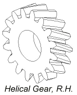
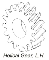
· In the Gear Type box select either the Helical R.H. or Helical L.H. from the drop down box.
· If the shafts are not parallel you will need to switch the helical direction of one of the gears. When helical is the first selected the other gear is automatically specified as the other hand.
· Selecting helix gear type enables the Helix angle input box. Enter the desired helix angle. This value must be greater than zero.
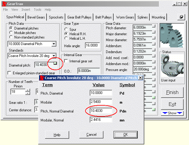
· To change the diametral pitch or module click on the More information button in the upper right hand corner of the Diametral pitch text box. Selecting helix gear type enables the text boxes to be edited. Enter the desired value in one of the four boxes. The other values will update accordingly. Click OK to apply the values.
· Enter a value for the face width in the Face width box.
· In the Number of Teeth box enter or use the spin box to change the number of teeth for the gear and the pinion.
· Enter a value for the tooth Backlash by clicking on the More information button in the upper right hand corner of the Backlash text box.
· Check the Create Tooth Pattern if you would like the tooth to be patterned.
· If the Create Tooth Pattern is checked, the Teeth to Draw box becomes enabled. If it is desired to pattern the tooth other than a full pattern then input the number of teeth to be drawn. This can be changed using SolidWorks after the part is drawn simply by editing the definition of the Tooth Pattern.
· If the Internal gear set check box is selected, enter a value for the outside diameter. This value must be larger than the dedendum circle value.
· Make any necessary changes to the hub mounting.
· Click on the Finish button to complete the gear.


