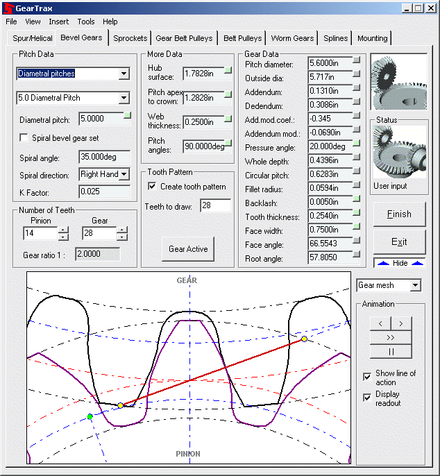
To create a bevel gear:
· Select the desired Diametral Pitch from the drop down box.

· Enter a value for the face width.
· Select the appropriate tooth proportion.
· Enter or use the spin box to change the number of teeth.
· Enter a value for the tooth clearance. See help for standard values for different diametral pitches.
· Check the Create tooth pattern if you want the tooth cut to be patterned.
· If the Create tooth pattern is checked, the Teeth to draw box becomes enabled. If it is desired to pattern the tooth other than a full pattern then input the number of teeth to be drawn. This can be changed after the part is drawn simply by editing the definition of the CirPattern1.
· Enter the pitch angle of the gear set (if other than 90).
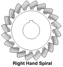
· To create a spiral bevel gear place a check in the Spiral bevel gear set box.
· Set the Spiral direction. The hand of the spiral is indicated by the direction in which the teeth curve away from the axis. The mating gear is always the opposite hand.

· Enter the K Factor for circular tooth thickness. This value can be found in Machinery’s Handbook in the 24th and earlier editions.
· Enter a value for the Hub Mounting Surface. This value should be between the Min/Max Hub Mounting values. If the mounting value is not between these values the base feature may not revolve properly.
· The pitch and outside diameters are driven dimensions.
· Make any necessary changes to the Hub Mounting.
· Click on the Finish button to complete the gear.