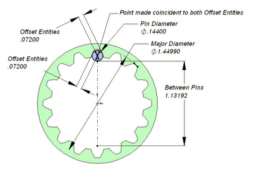
· Between pin measurements can be created manually and can be used to verify data.
· Create a new sketch on the face of the gear.
· Select a single tooth spline and create an offset entity equal to ½ of the pin diameter.
· Select the spline on the other side of the tooth space. Create another offset entity equal to ½ the pin diameter.
· Add a point on one of the new offset entities.
· Add a coincident relationship between the point and the offset entity.
· Add a circle with the center on the point. Dimension the circle equal to the pin diameter.
· Add a centerline to the sketch.
· Add a midpoint relationship between the centerline and the center of the gear.
· Add a coincident relationship between the pin outside diameter and an end point of the centerline.
· Add a coincident relationship between the pin center point and the centerline.
· Add the between the pins dimension by adding a dimension to the length of the centerline.

· Sample of a manual verification of between the pins measurements using SolidWorks.
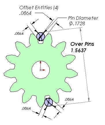
· If the gear has an odd number of teeth you will need to create the sketch with 2 pins.

Sample of a manual verification of over the pins measurements using SolidWorks.