Spur Gears
Addendum is the length of the tooth from the pitch diameter to the major diameter. This value cannot be changed directly unless GearTeq is in the “Free Form” mode.
Addendum Modification is the amount of addendum change of a modified tooth. This value can be positive or negative. If the sum of change to a pair of gears equals zero then there is no change to the center distance.
A positive value will increase the addendum length and a negative value will decrease the addendum length.
If GearTeq is in the “Free Form” mode, the value will be unused.
Addendum Modification Coefficient
Addendum Modification Coefficient is the ratio of change of a modified tooth. This value can be positive or negative. If the sum of change to a pair of gears equals zero then there is no change to the center distance.
A positive value will increase the addendum length and a negative value will decrease the addendum length.
If GearTeq is in the “Free Form” mode, the value will be unused.
AGMA Class sets the AGMA Class for this component.
Backlash is the thinning (or thickening, if a negative value) of the tooth profile after any modification to the tooth form. This backlash is achieved by rack shift and does not affect the diameters. See addendum modification for tooth thinning or thickening that also affects the diameters.
Backlash Arc Minute is the angular value in minutes (1/60 of a degree) of the backlash value.
Blank OD of Internal Gear is the diameter of the blank used to create the internal gear. The diameter must be large enough for the tooth cut in CAD.
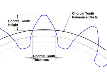
Chordal Tooth Height is the length of the tooth portion to be measured at which the chordal tooth thickness is calculated. Twice the chordal tooth height plus the chordal tooth reference circle should equal the outside diameter of the gear.
Chordal Tooth Reference Circle
Chordal Tooth Reference Circle is the diameter of the datum circle at which the chordal tooth thickness is measured. The chordal tooth reference circle should be equal to the outside diameter of the gear minus twice the chordal tooth height.
Chordal Tooth Thickness is a straight-line measurement across a single tooth at the chordal tooth reference circle.
Chordal Tooth Thickness Minimum
Chordal Tooth Thickness is a straight-line measurement across a single tooth (maximum actual tooth thickness minus tooth thickness tolerance) at the chordal tooth reference circle.
Circular Pitch is the arc length of a single pitch at the pitch diameter.
Code Tooth Thickness sets the tooth thickness code class for this component.
Addendum Coefficient is a constant that is divided by the diametral pitch to determine the length of the addendum before any modification. The addendum length of a 10 diametral-pitch gear with an addendum coefficient of 0.8 is 0.080in.
The whole depth is equal to the sum of twice the addendum coefficient and the clearance coefficient divided by the diametral pitch.
Clearance Coefficient is a constant that is divided by the diametral pitch to determine the clearance in the root of the gear tooth.
The whole depth is equal to the sum of the clearance coefficient and twice the addendum coefficient divided by the diametral pitch.
Coefficient, Clearance Additional
Coefficient, Clearance Additional is a linear value (not a coefficient) that is added to the dedendum to increase the amount of clearance between the tooth tip of the mating gear and the root of this gear. This is used with the AGMA fine pitch standards only.
Fillet Coefficient is a constant that is divided by the diametral pitch to determine the radius of the hob tip that creates gear tooth root.
Contact Diameter is the diameter where the mating gear tip first makes contact with the component.
Contact Length, Approach and the recess length equal the total contact for a pair of gear teeth.
Contact Length, Recess and the approach length equal the total contact for a pair of gear teeth.
Contact Ratio is the ratio of the arc of action to the circular pitch. This value should be over 1.4 to assure a smooth transfer of load from one pair of teeth to the next pair of teeth.
Dedendum is the radial length of the tooth between the pitch diameter and the minor diameter.
Base Diameter is a diameter that is tangent to the pressure angle. The involute curve cannot be within this diameter.
Diameter, Base Normal is a diameter that is tangent to the normal pressure angle.
Major Diameter is the outside diameter of a gear.
Minor Diameter is the root diameter of a gear.
Pitch Diameter is the theoretical diameter of the gear.
Normal Pitch Diameter is the theoretical diameter of the gear normal to the cutter.
Pitch Diameter, Operating is a theoretical diameter at which a set of gears meshes. It normally equals the pitch diameter except when either of the gears is modified or the center distance has been modified.
The true involute form (TIF) diameter is the smallest diameter of the involute curve.
External Internal Rack defines the component as an external gear, internal gear or a rack.
Face Width is the length of the tooth parallel to the shaft.
The Fellows Stub Denominator sets the denominator for the Fellows Stub standard. The Fellows Stub standard must be selected to change this value. This value must be equal to or less than the diametral pitch
The user may specify any combination of nominator/denominator for the Follows Stub standard as long as the denominator is a value greater than the nominator. The standard ratios established by the Fellows Gear Shaper Co. are 4/5, 5/7, 6/8, 7/9, 8/10, 9/11, 10/12 and 12/14.
Fillet Radius defines the radius on the tip of the cutter, which forms a trochoidal curve tangent to the tooth root.
Gear Standard sets the AGMA, DIN, JIS, PGT or other standards for the component.
Helix Angle is the angle of the tooth from the shaft. A zero angle would be parallel to the shaft and would define a spur gear. An angle other than zero would define a helical gear.
Helix Direction defines the direction of the angle. The teeth on a left hand helical gear on a horizontal surface lean to the left.
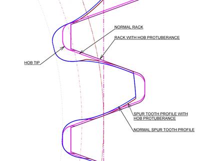
Hob Protuberance is the amount of undercutting of the involute surface created by the hob. The fillet remains unchanged except for a slight increase in length.
Keyway defines if a standard keyway is to be created. Select none or the standard. The key size is determined by the bore size. The part must have a valid bore for the keyway to be created.
Keyway Position defines the angular position of the keyway relative to the Tooth Center or the Space Center.
Lead of the tooth helix. Lead is equal to the pitch diameter multiplied by PI times the Cotangent of the helix angle.
Manufacturing Method defines the method to be ‘used’ for manufacturing the tooth cut. Select Hobbing or Full Fillet Radius.
Mate Angle is the angle of the part to its gear mated parent in the transverse plane. The angle is counter clockwise starting at the 3:00 position.
Runout is the maximum variation of the distance between a surface of revolution and a datum surface, measured perpendicularly to the datum surface, per AGMA 2000-A88.
Measurement Over/Under Pins is the measurement over two pins diametrically opposed in a gear and is normally used for inspection. The measurement is over pins for external gears and under pins for internal gears. GearTeq will calculate the tooth thickness for an external gear and the space width for internal gears if a value is entered for the over/under pin measurement.
Measurement Over/Under Pins Minimum
Measurement Over/Under Pins Minimum is the measurement over two pins diametrically opposed in a gear and is normally used for inspection. Measures the tooth thickness minus the total tooth thickness tolerance.
Modification Profile APL Amount
Modification Profile APL Amount is the amount of modification to the involute profile above the pitch line. The modification can be linear or parabolic.
Modification Profile APL Diameter
Modification Profile APL Diameter is the diameter above the pitch line at which the profile modification starts. The value must be greater than or equal to the pitch diameter.
Modification Profile APL Length
Modification Profile APL Length is the length of the modification above the pitch line. The length is limited to the length of the addendum. It is prohibited from being within the pitch diameter. The modification can be linear or parabolic.
Modification Profile APL Type is the type of modification to the involute profile above the pitch line. Choose between None, Linear and Parabolic.
Modification Profile BPL Amount
Modification Profile BPL Amount is the amount of modification to the involute profile below the pitch line. The modification can be linear or parabolic.
Modification Profile BPL Diameter
Modification Profile BPL Diameter is the diameter below the pitch line at which the profile modification starts. The value must be less than or equal to the pitch diameter.
Modification Profile BPL Length
Modification Profile BPL Length is the length of the modification below the pitch line. The length is limited to the length of the dedendum. It is prohibited from being outside of the pitch diameter. The modification can be linear or parabolic.
Modification Profile BPL Type is the type of modification to the involute profile below the pitch line. Choose between None, Linear and Parabolic.
Module (transverse) is used in metric system gears. Module equals the normal module divided by the cosine of the helical angle.
Module Normal is used in metric system gears and is normal to the cutter. Module = 25.4 / diametral pitch.
Mounting Bushing Modeling specifies if the bushing should be created as a separate part or as part of the component.
Mounting Bushing Side specifies which side of the component the mounting is referenced.
Name defines the name of the part.
Number of Teeth defines the number of teeth for the component.
Path defines the name of the folder where the component files are stored.
Part Color sets the color of the component. If the component is the active component then the color used for display is determined by the Color_Active_Component option in the Options menu. To get an active component to be displayed in its specified color, set the Color_Active_Component option to Transparent.
Pin Diameter defines the diameter of the pins or wires used with Measurement of Pins. A user defined pin diameter may be entered. To reset the value to the standard value select Tools>Reset Over/Under Pin Measurement in the GearTeq menu.
Pitch Depth of Rack is the distance from the pitch line to the back of the rack.
Diametral Pitch is used in imperial system gears. This defines the diametral pitch in the transverse plane.
Diametral Pitch, Normal is used in imperial system gears and is normal to the cutter.
Pressure Angle is the angle of the tooth at the pitch diameter. This is sometimes referred to as the transverse pressure angle.
Pressure Angle, Normal is the angle of the tooth at the pitch diameter normal to the cutter.
Pressure Angle, Working is the angle of the tooth at the pitch diameter. This is normally the same as pressure angle unless either gear in the set has been modified or the center distance has been changed.
Roll Angle at Custom Diameter provides the user with a method to calculate a roll angle at any valid diameter. Entering a new diameter in this property will calculate the roll angle for the entered value. The value must be greater than the base diameter.
Roll Angle at the Major Diameter is displayed.
Roll Angle at Profile Modification Above Pitch Line
Roll Angle at the start of the profile modification above the pitch line is displayed if a modification is specified.
Roll Angle at Profile Modification Below Pitch Line
Roll Angle at the start of the profile modification below the pitch line is displayed if a modification is specified.
Roll Angle at the TIF Diameter is displayed.
Shrinkage Rate defines the shrinkage rate for plastic gears. This is only used when inserting a tooth cut profile. The value entered must be less than 0.0100 (1%), 0.0025 = 0.25%
Span Measurement is a straight-line measurement across the Number of Teeth to Gage Over. This value is read-only.
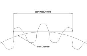
Span Measurement Minimum is the minimum straight-line measurement across the Number of Teeth to Gage Over using the tooth thickness minimum value. This value is read-only.
Span Measurement, Teeth to Gage Over
Span Measurement, Teeth to Gage Over define the number of teeth that are used in conjunction with Span Measurement.
Teeth to Pattern defines the number of teeth to pattern when creating the model in CAD. The options are All, None, or First 10. If this is set to All, GearTeq will create a pattern that contains all the teeth. This might be very time consuming if there are a large number of teeth and/or the component is a helical gear. If this is set to none, then a pattern will not be created. Set this to ‘First 10’ to create a pattern with 10 teeth that can easily be expanded in the CAD system.
Profile Tolerance is the permissible amount of profile variation in the functional profile, designated by a specified “K” chart envelope. Plus material at the tip, which increases the amount of variation outside the functional profile, is not acceptable. Minus material beyond the start of tip break can be disregarded.
Tooth Alignment Tolerance is the permissible amount of tooth alignment variation, designated by the specified “K” chart envelope. Tolerance values in this standard are normal to the tooth surface.
Tooth Thickness Tolerance is the permissible amount of tooth thickness variation.
Total Composite Tolerance is the permissible amount of total composite variation, which is the total change in center distance while the gear being tested is rotated one complete revolution during double flank composite action test.
Total Composite Index.
Tooth Thickness is the arc thickness of the tooth at the pitch diameter.
Tooth Thickness at Major Diameter
Tooth Thickness at Major Diameter is the arc thickness of the tooth at the tip of the gear.
Tooth Thickness, Normal is the arc thickness of the tooth at the pitch diameter normal to the cutter.
The Tooth Thickness Tolerance is a user input property that defines the tolerance according to DIN 3967.
Topping Adjustment will shorten the length of the addendum by this value and the major diameter by twice this value. This value must be equal to or greater than zero and less than the unadjusted addendum.
Units sets the measurement units for the component; select Inches or Metric.
Upper Tooth Thickness Allowance
The Tooth Thickness Allowance is a user input property that defines the allowance according to DIN 3967.
Pitch Variation is the algebraic (+ or -) plus or minus difference in the transverse plane, between the true position pitch and an actual pitch measurement. If measured in a plane other than the transverse plane, a correction using the appropriate helix angle must be applied to the measured value according to AGMA 2000-A88.
Whole Depth is the depth of the tooth (from the major diameter to the minor diameter).
The whole depth is equal to the sum of the clearance coefficient and twice the addendum coefficient divided by the diametral pitch.