GearTeq Menus
New removes all components and assembly positions. GearTeq is ready to start a new assembly or component.
Open Components opens a previously saved component document. Component documents have .gtc as the file extension.
Open Assemblies opens a previously saved assembly document. Assembly documents have .gtqasm as the file extension.
Open Legacy Assemblies opens older GearTeq assembly files created in the 2011 and earlier versions. Legacy Assembly files have .gta as the extension.
Save Component saves the active component. The component name will change to reflect then name of the file. Component files have .gtc as the extension.
Save Component As saves and changes the name of the active component. The component name will change to reflect the name of the file. Component files have .gtc as the extension.
Save All saves the assembly. The assembly will change to reflect the name of the file. Assembly files have .gtqasm as the extension and component files have.gtc as the extension.
Save All As saves and changes the name of the assembly and components. The assembly will change to reflect the name of the file. Assembly files have .gtqasm as the extension and component files have .gtc as the extension.
Save Assembly As saves and changes the name of the assembly. The assembly will change to reflect the name of the file. Assembly files have .gtqasm as the extension.
Lock/Unlock Active Component opens a dialog box that allows the user to lock or unlock a component. The pass code is simply an integer with a value between 200 and 32,000. When a component is locked the property background color will be gray.
Remove Active Component removes the active component from the assembly. The component must not be a parent to any other components.
Remove Unused Components removes any orphaned components that may have been left in the assembly if there were changes to the components specified in an AP. A message box will prompt the user with which components can be removed.
Print GearTeq Window prints the GearTeq window, including borders.
Capture GearTeq screen to a file
Capture GearTeq screen to file captures the GearTeq screen, including borders, to a bit map file.
Capture GearTeq screen to the clipboard
Capture GearTeq screen to the clipboard captures the GearTeq screen, including borders, to the clipboard.
Capture GearTeq screen and open in bit map editor
Capture GearTeq screen and open in bit map editor captures the GearTeq screen, including borders, to the default bit map editor.
Empty Clipboard clears the clipboard of any data. This frees up any memory the screen capture is using.
Convert GearTrax file opens an existing GearTrax file. Save it as a GearTeq component to complete the conversion to GearTeq.
Recent files displays recently used files. Click on the recent file to open it in GearTeq.
Exit closes GearTeq. The user is prompted to save any unsaved data.
Create CAD Models and Assembly
Create CAD Models and Assembly opens the Create CAD Models dialog window.
Quick Create > Create Active Component
Quick Create>Create Active Component creates a CAD Model of the active component without any options.
Quick Create > Insert Tooth Cut Entities
Quick Create>Insert Tooth Cut Entities draws the tooth cut entities of the active spur or spline in the active sketch in CAD.
Edit CAD Models opens the dialog window for editing CAD Models.
Component Template File opens a dialog box for specifying the CAD template to be used when creating new CAD models.
Assembly Template File opens a dialog box for specifying the CAD template to be used when creating new CAD assemblies.
Annotation Selector loads the annotation definitions into the property grid for the active component. Items set to true will be used when annotating a drawing file.
(SolidWorks users only)
Insert Annotations will insert a note into a view of a drawing document.
To insert an annotation a few things must be set:
First, the annotation selector must be active. It doesn’t need to be the selector for the current active CAD file but it should be the same type of component. If the same annotation properties are to be used for a variety of components, then a generic component can always be used to create the annotation. This will relieve the user of the task of having to set each of the properties to true or false for each new component.
The CAD document must be a drawing.
A drawing view must be active (a green box highlights the view).
When inserting an annotation there is a choice of adding it as text or as a table. In either case, the information is retrieved from the part file. If the part file data changes, this will be updated automatically. All information is related to the part file’s Menu>Properties…>Configuration Specific>Apply to:> option.
If inserting as text, a font such as “Lucida Console” may be desired because it will align the columns with its even character spacing.
Redraw – fit all redraws the assembly to fit on the screen with the front view and resets the drive position to zero.
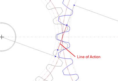
Show Line of Action, if checked, will display the line of action on spur gear pairs with gear mates.
Show Over/Under Pins, if checked, will draw a red circle between a pair of spur gear teeth.
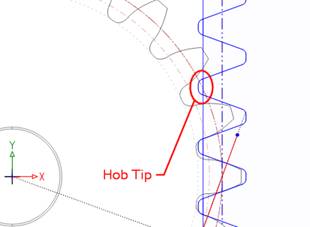
Show Hob Tip on Rack, if checked, will display the hob tip on all rack type components.
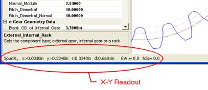
Show XY Readouts, if checked, will display the x, y, r and d in the task bar for the cursor position in the current screen plane.
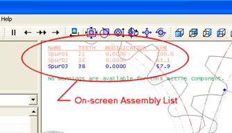
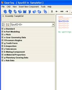
Show Assembly On-Screen List, if checked, will display the assembly list in the upper left hand corner of the drawing screen.
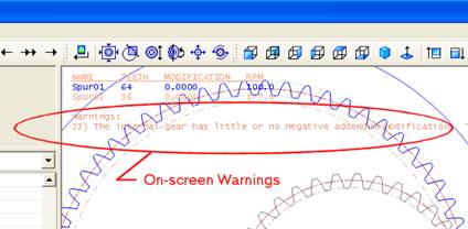
Show Warnings On-screen, if checked, will display any available warnings in the upper left hand corner of the drawing screen.
Collapse Grid collapses the property grid to the categories. The short cut key is F11.
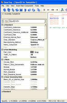
Expand Grid expands the property grid to display all items. The short cut key is F12.
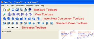
Standard
If checked, the Standard tool bar will be displayed.
View
If checked, the View tool bar will be displayed.
Standard Views
If checked, the Standard Views tool bar will be displayed.
Simulation
If checked, the Simulation tool bar will be displayed.
Insert New Component
If checked, the Insert New Component tool bar will be displayed.
Deviation Chart opens the deviation chart window. This menu item is normally disabled unless the active component is a DIN spline. The short cut key is F3.
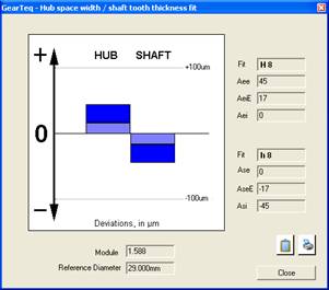
Values of the components can be changed in the property grid and the chart is updated automatically.
CPI (Common Properties Interface)
The shortcut key to open the CPI is "F2"
The CPI is an interface that allows the user to modify more than one component without switching the active component. The CPI will change for different types of components or planetary gear sets.
The CPI is not available for chain sprockets, timing belt pulleys and Vee belt pulleys.
Insert a New Assembly Position
Insert a New Assembly Position adds a blank assembly position into the assembly.
Clicking ‘New Spur or Helical...’ opens a dialog box to insert a new spur or helical gear into the assembly.
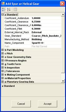
Click “Accept” to add the new component or “Cancel” to continue without adding the component. The parameters for the new component can be changed at any time, before or after adding it to the assembly.
The short cut key for this menu item is Ctrl+S.
Clicking ‘New Bevel Gear...’ opens a dialog box to insert a new bevel gear into the assembly.
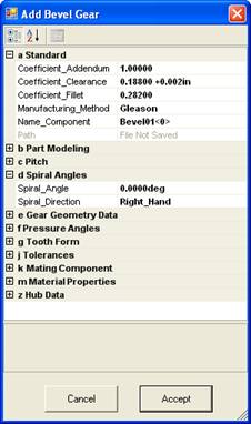
Click “Accept” to add the new component or “Cancel” to continue without adding the component. The parameters for the new component can be changed at any time, before or after adding it to the assembly.
The short cut key for this menu item is Ctrl+B.
Clicking ‘New Chain Sprocket...’ opens a dialog box to insert a new chain sprocket component into the assembly.
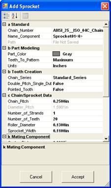
Click “Accept” to add the new component or “Cancel” to continue without adding the component. The parameters for the new component can be changed at any time, before or after adding it to the assembly.
The short cut key for this menu item is Ctrl+C.
Clicking ‘New Gear Belt Pulley...’ opens a dialog box to insert a new gear belt pulley component into the assembly.
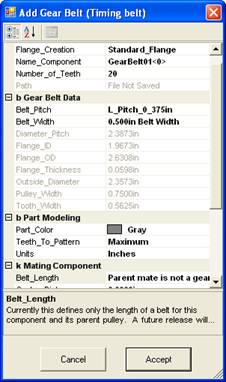
Click “Accept” to add the new component or “Cancel” to continue without adding the component. The parameters for the new component can be changed at any time, before or after adding it to the assembly.
The short cut key for this menu item is Ctrl+G.
Clicking ‘New Belt Pulley...’ opens a dialog box to insert a new belt pulley component into the assembly.
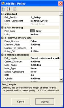
Click “Accept” to add the new component or “Cancel” to continue without adding the component. The parameters for the new component can be changed at any time, before or after adding it to the assembly.
The short cut key for this menu item is Ctrl+P.
Clicking ‘New Worm Gear Set...’ opens a dialog box to insert a new worm gear pair.
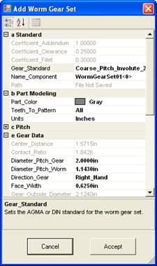
Click “Accept” to add the new component or “Cancel” to continue without adding the component. The parameters for the new component can be changed at any time, before or after adding it to the assembly.
The short cut key for this menu item is Ctrl+W.
Clicking ‘New External Spline...’ opens a dialog box to insert a new external spline component into the assembly.
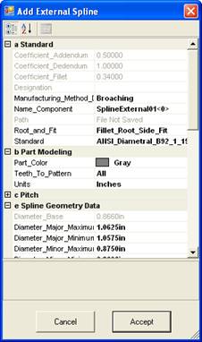
Click “Accept” to add the new component or “Cancel” to continue without adding the component. The parameters for the new component can be changed at any time, before or after adding it to the assembly.
The short cut key for this menu item is Ctrl+E.
Clicking ‘New Internal Spline...’ opens a dialog box to insert a new internal spline component into the assembly.
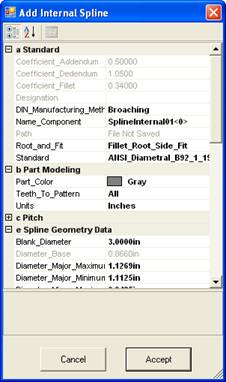
Click “Accept” to add the new component or “Cancel” to continue without adding the component. The parameters for the new component can be changed at any time, before or after adding it to the assembly.
The short cut key for this menu item is Ctrl+I.
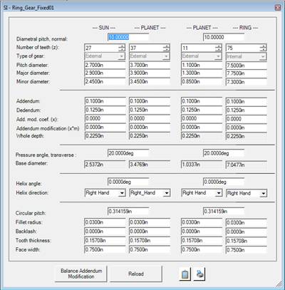
Clicking “New Planetary Set…” opens a dialog box that can be used to create a single stage planetary gear set.
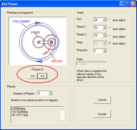
Use the index buttons to cycle between the available planetary arrangements. These figure numbers correspond to the figure numbers in Machinery’s Handbook.
Select the number of planets for the set. The angular placement of the planets is displayed. The possible number of planet positions is equal to the sum of teeth in the sun and the ring. GearTeq displays the planet position of the nearest equally spaced position.
The user may change the number of teeth using the dialog box, or later, in the property grid for each of the components. GearTeq will only automatically adjust the number of teeth for one of the components as the other components are changed in the Add Planet dialog window. Select which component you would like GearTeq to change automatically by selecting the Auto Adjust bullet. After the parts are displayed in GearTeq, the user will be responsible for assuring that the number of teeth is appropriate if any one component’s number of teeth is changed.
The Ring Plus option will add the number specified to the number of teeth of the ring.
Individual planetary components cannot be opened in GearTeq unless they are in the original assembly.
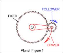
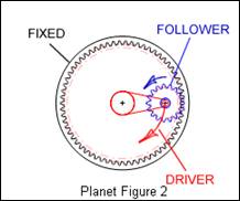
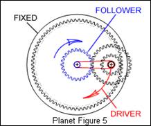

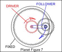
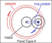
Standard Planet Layouts Available in GearTeq
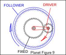
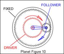
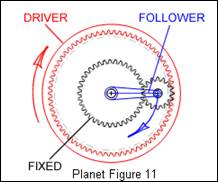
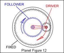
Standard Planet Layouts Available in GearTeq
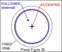
Cycloidal gear sets are very high ratio assemblies. Ratios between 30:1 and 350:1 are obtainable.
To create a cycloid (cycloidal) gear set, use the Add Planetary Set module. Select ‘Figure 30’ which will create an internal and external gear set. The default values are for a set with a ratio of 99:1. The number of teeth for the ring gear is 100 and the external gear is 99. The Ring plus is set to 0 and cannot be changed. The number of planets is set to1 and should not be changed.
The default addendum modification coefficient is –0.450 for both components. After accepting the settings ‘Zoom Area’ the tooth mesh at the 3:00 position. You will notice that the teeth are not in contact. This is NORMAL.
Zoom the area where the line of action intersects the teeth. Notice the contact for the gear teeth. The corresponding contact for the other side of the tooth is vertical of this position. The default backlash is 0.000, which can be changed to suit the application.
The carrier plate is created by the CAD system. The offset of the eccentric should be equal to the center distance displayed for the external component. It is up to the designer to select the best method to tie the external component to an output device, such as a plate. This plate may contain a number of protrusions, such as cam followers, which roll in the same number of holes in the external component. The size of these holes should be equal to the diameter of the follower plus twice the eccentric dimension.
The output plate is concentric to the input of the eccentric and ring gear.
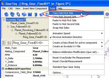
Clicking ‘Copy Hub First Side‘copies the hub first side data to the copy hub clipboard for pasting to the second side hub or to either side of other components.
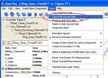
Clicking ‘Copy Hub Second Side’ copies the hub second side data to the copy hub clipboard for pasting to the first side hub or to either side of other components.
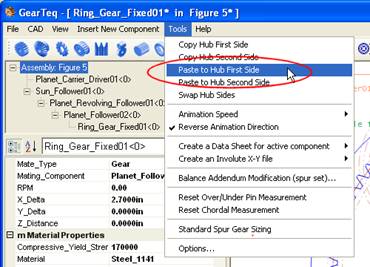
Clicking ‘Paste to Hub First Side’ pastes the data stored in the hub copy clipboard to the hub first side of the current active component.
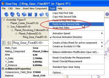
Clicking ‘Paste to Hub Second Side’ pastes the data stored in the hub copy clipboard to the hub second side of the current active component.
Clicking ‘Swap Hub Sides’ swaps the hub data of the two sides for the current active component.

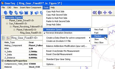
Animation Speed sets the animation speed for the simulation. The slower the speed the finer the angular steps in the simulation. Select between Very Fast, Fast, Medium, Slow and Very Slow.
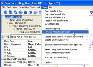
Clicking ‘Reverse Animation Direction’ reverses the direction of the simulation.
Balance Addendum Modification…
The Balance Addendum Modification menu option opens a dialog window that can adjust the addendum modification for the active gear and its mate. The mate must be a spur gear with a gear mate.
The change in addendum modification coefficient can be automatically estimated. The addendum modification coefficients for the current component and its mating component can be balanced by the following formula:
x1 = 1 / 3 * (1 - 1 / u) + (x1 + x2) / 1 + u
where u is the gear ratio
x1 and x2 are the addendum modification coefficients of the pinion and the gear, respectively. The pinion is the gear with the lesser number of teeth.

The user may manually enter values for the sum and individual addendum modification coefficients. The screen will be updated to reflect these changes.
The slider bar may also be used to change the distribution of the modification.
Click the Cancel button to restore the original values and close the window.
Click the Accept button to use the values and close the window.
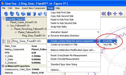
Create a Data Sheet for active component
Excel file
Clicking ‘Excel file’ creates a data sheet of the active component in Microsoft Excel, if available.
Text file
Clicking ‘Text file’ creates a data sheet of the active component in Microsoft Notepad, if available.
Comma Separated Values (CSV) file
Clicking ‘Comma Separated Values file’ creates a data sheet in Microsoft Notepad, if available, that can be imported into most spread sheet programs.
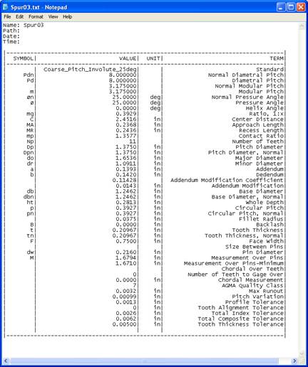
Sample of a data sheet created as text file
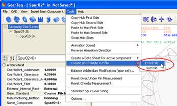
This option is only available for spur gears and splines.
Excel file
Clicking ‘Excel file’ creates an X-Y file of the points along the involute tooth in Microsoft Excel, if available.
Text file
Clicking ‘Text file’ creates an X-Y file of the points along the involute tooth in Microsoft Notepad, if available.
Comma Separated Values (CSV) file
Clicking ‘Comma Separated Values’ creates an XYZ file of the points along the involute tooth in Microsoft Notepad, if available. The Z column will have a 0.000 value.

Sample of an XY file created as a text file
Depending on the type of active component, the Create a DXF file menu command can create a DXF file of the revolve geometry or the tooth cut entities. A message box will allow the user to open the file in the default DXF program.
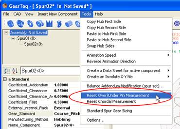
Reset Over/Under Pin Measurement
Clicking ‘Reset Over/Under Pin Measurement’ resets the over/under pin diameter if the user has manually changed the value. The over/under measurements are updated accordingly.
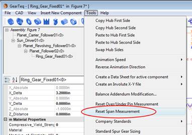
Clicking ‘Reset Span Measurement’ resets the number of teeth to gage over if the user has manually changed the value. The span measurement is updated accordingly.
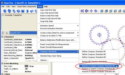
Company Standards allows the user to configure up to three different company standards.
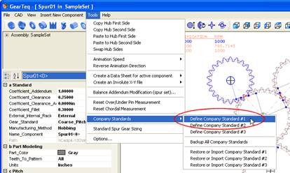
Select one of the three company standards to load it into the property grid. Make any changes to the standard and then use the component selector to switch back to a component.
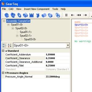
Coefficient Addendum
Coefficient Addendum defines the constant that is used to calculate the length of the addendum.
addendum = coefficient addendum / diametral pitch (inches)
addendum = coefficient addendum * module (millimeters)
Valid values are greater than 0 and less than 2.
Coefficient Clearance
Coefficient Clearance defines the constant that is used to calculate the length of the addendum.
dedendum = (coefficient addendum + coefficient clearance) / diametral pitch (inches)
dedendum = (coefficient addendum + coefficient clearance) * module (millimeters)
Valid values are greater than or equal to 0 and less than or equal to 1.
Coefficient Clearance Additional
Coefficient Clearance Additional is a linear dimension that defines the amount of additional length to be added to the dedendum. This value does not take into consideration the units (inches or millimeters) of the component.
Coefficient Fillet
Coefficient Fillet defines the constant that is used to calculate the length of the addendum.
The hob tip fillet radius = coefficient fillet / diametral pitch (inches)
The hob tip fillet radius = coefficient fillet * module (millimeters)
Valid values are greater than 0 and less than or equal to 1.
Standard
Standard is a read only display of which standard is being edited.
Pressure Angle Normal
Pressure Angle Normal defines the pressure angle for the standard.
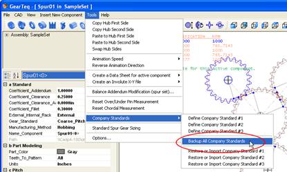
Backup All Company Standards allows the user to backup the company standards in a location that will not be destroyed when removing or installing a new version of GearTeq. This can also be used to store the standards so that other users can have access to them.
Restore or Import Company Standards
Restore or Import Company Standards allows the user to restore company standards after a new installation of GearTeq or to import the company standards from another location.
Standard Spur Gear Sizing loads the spur gear sizing module into the property grid.

The user input parameters are:
a) Diametral pitch P
b) Module M
c) Gear reduction ratio mg, must be greater or equal to 1.0
d, e, f) Pinion torque, in-lbs, ft-lbs or Nm
g) Load factor K
h) Material hardness Bhn, Brinell hardness number, the material must be steel
i) Material factor Km, 0.6 for through-hardening steels, 0.9 for case-hardening steels
j) 20 or 25 degree pressure angle
k) Dedendum factor Ko, values of 1.25 or 1.35 are allowed
l) Fillet coefficient rf, Assumed to be 0.30 or 0.21 for 25 degree pressure angle with 1.35 dedendum factor gears
The calculated values are:
m) Pinion Pitch Diameter
m) Pinion, suggested number of teeth
n) Gear Pitch Diameter
n) Gear, suggested number of teeth
o) Calculated Gear Ratio
p) Calculated Face Width
q) Calculated Center Distance
Open install folder using Explorer
GearTeq is compiled and published as a "Click-once" application; therefore the installation folder is not in the program folder like it is for most programs. The installation folder can be opened with this command.
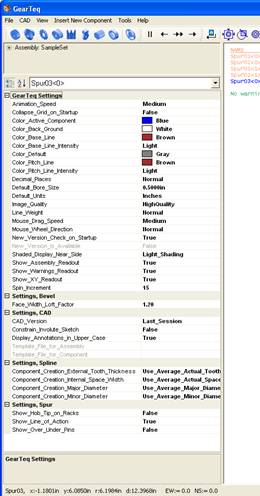
Options...
The Options settings are made available through the GearTeq menu item Tools>Options.
Clicking ‘GearTeq Help Topics’ opens the GearTeq help topics.
Clicking ‘GearTeq Quick Start Guide’ opens a PDF of the quick start guide. Adobe Acrobat must be installed on the computer.
Registration...
Clicking ‘Registration’ loads the registration information into the property grid.
Create Email with registration information
Clicking ‘Create Email with registration information’ opens the default email with the information specified.
Clicking ‘License’ opens Notepad with the license agreement.
Check for Updates will check the Camnetics’ web site for a newer version of GearTeq. A message box will tell the user whether a newer version is available or not. The new version will not be downloaded or installed.
Clicking ‘About GearTeq…’ opens the About window. Camnetics addresses are listed along with a link to the web site. The version of GearTeq that is installed is displayed.