Assembly Positions (AP)
Assembly positions (AP) determine the location and type of mating for each of the components. The APs also contain information about mating sets of components. For example, the center distance will displayed for a set of spur gears. An assembly may contain any number of APs with each AP specifying the same gear component. Each AP could specify a different method for controlling the center distance.
There are two ways to activate an AP and have its properties displayed in the property grid. The APs are listed in the component select drop down box that is just above the property grid. Each AP is proceeded by a <XYZ> designation. Drop down the list and click on the desired AP. The second method for selecting an AP is to click on the AP listed in the assembly tree view, then right click on the item to drop down a menu, which will allow the selection of the assembly, component or the AP.
Each AP has a set of categories. What categories are used depends on the type of component that is selected for that AP.
Click this box to open a drop down list of the components in the assembly.
The name of this position used in the Component Selector and the Assembly Tree. Other positions can also specify this position as their Assembly Mating Position.
Gear Ratio is the rotational ratio between a parent component and the active component.
Mate Angle is the angle of the part to its gear mated parent in the transverse plane. The angle is counter clockwise starting at the 3:00 position.
Click Mate Type to open a drop down list of the type of mates available. This specifies the type of mate a part has to its parent part. Each part can have only one parent mate while a part may have a number of child mates.
Mating Assembly Position is a user selectable drop down list of all the APs. The current AP is on the list but cannot be selected. Also, any AP that would result in a circular mating cannot be selected.
RPM is the revolutions per minute of the active component.
X Absolute is the distance between the X origin of the current component and the X origin of the assembly.
X Delta defines the X distance from the mating component. Entering a value will react differently depending on the type of component and the type of mating relationship it has to its parent component. For example, changing the value of a spur gear with a gear relationship to its parent spur gear will also change the Y delta. The value entered must be less than the center distance for the pair. Changing the value for a belt pulley with a belt relationship to its parent belt pulley will not change the Y delta but will change the center distance.
Y Absolute is the distance between the Y origin of the current component and the Y origin of the assembly.
Y Delta defines the Y distance from the mating component. Entering a value will react differently depending on the type of component and the type of mating relationship it has to its parent component. For example, changing the value of a spur gear with a gear relationship to its parent spur gear will also change the X delta. The value entered must be less than the center distance for the pair. Changing the value for a belt pulley with a belt relationship to its parent belt pulley will not change the X delta but will change the center distance.
Z Distance is the distance between the current component and its parent component on the transverse plane. Normally this is zero, as for a pair of spur gears whose faces are running on center with each other.
Z Delta
Z Absolute is the distance between the Z origin of the current component and the Z origin of the assembly.
Center Distance Belt Pulley is the distance between the centers of two belt mated pulleys.
Vee Belt Length is the length of the belt along the pitch line of this component and its mating belt pulley parent component. Idlers and other belt pulley components are not taken into consideration.
Sum of Pitch Angles defines the sum of the pitch angles for this component and its parent component.
Center Distance Chain is the distance between the centers of two chain mated sprockets.
Chain Length is the length of the chain along the pitch line of this component and its mating chain sprocket parent component. Idlers and other chain sprocket components are not taken into consideration.
Even Full Pitches defines the number of full pitches in the length of chain.
Center Distance Gear Belt is the distance between the centers of two belt mated pulleys.
Gear Belt Length defines the simple length of a belt between two gear belt pulleys. Entering a value will change the center distance. Changing the center distance will change this value.
The actual clearance maximum is based on the size and class of the spline. The mate of the component must be a complimentary spline with a shaft mate for values other than 0 to be displayed.
The actual clearance minimum is based on the size and class of the spline. The mate of the component must be a complimentary spline with a shaft mate for values other than 0 to be displayed.
The effective clearance maximum is based on the size and class of the spline. The mate of the component must be a complimentary spline with a shaft mate for values other than 0 to be displayed
The effective clearance minimum is based on the size and class of the spline. The mate of the component must be a complimentary spline with a shaft mate for values other than 0 to be displayed.
This section is for a spur and its gear mate.
Center Distance Actual is the distance between this component and the parent after any changes.
If the center distance locked property is set to true, then the value entered will be used whether it is valid or not.
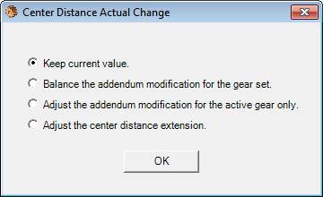
If the active component is a spur gear with a gear mate to another spur gear then changing the center distance will allow the user to change the addendum modification of the active component and the mating component. The following dialog box is displayed:
Select the "Keep current value" option to keep the value before the new value was entered.
Select the "Balance the addendum modification for the gear set" option change the addendum modification coefficient for the active component and its mating gear by the following formula:
x1 = 1 / 3 * (1 - 1 / u) + (x1 + x2) / 1 + u
where u is the gear ratio
x1 and x2 are the addendum modification coefficients of the pinion and gear, respectively
Select the "Adjust the addendum modification for the active gear only" option to change only the addendum modification of the active component.
Select the "Adjust the center distance extension" option to change the center distance extension. The center distance actual value will also change accordingly. No changes are made to the geometry of either gear, only the position on their assembly.
Tip: Change the center distance and accept the addendum modification to the active component. Then use the Tools>Balance Addendum Modification to redistribute the modification between the gear set (pair).
Center Distance Extension is a manually added value that extends the center distance of a pair of gears. This does not affect the geometry of either gear in the pair.
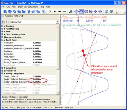
The increase in backlash is a result of the enter distance extension. The value displayed for the center distance extension backlash is approximate.
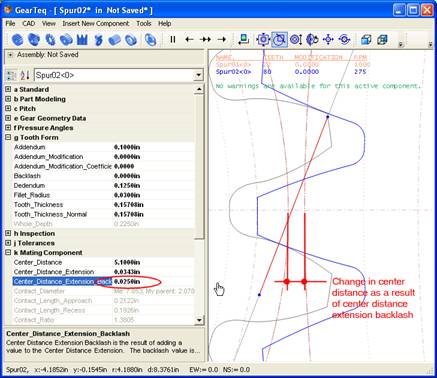
Center Distance Extension Backlash
The Center Distance Extension Backlash is a manually added value that increases the backlash on a set of gears without affecting the individual gear geometry. The change in the center distance is approximate relative to the change in backlash.
Center Distance Locked is a true or false value determining if the center distance should be calculated or fixed at a user input value as specified in the Center Distance Actual property.
Center Distance Standard is the calculated distance between this component and its parent after any addendum modification and before any center distance extension.
Contact Length Approach is the approach path of contact in involute gears. It is a straight line passing through the pitch point and the contact diameter of the active component.
Contact Length Recess is the recess path of contact in involute gears. It is a straight line passing through the pitch point and the contact diameter of the mating component.
Contact ratio is the ratio of the arc of action to the circular pitch.
Contact Ratio Face is the face contact ratio for a helical gear set. A value is displayed for a helical gear set when the parent component is a helical gear with a gear mate.
Contact Ratio Total is the total contact ratio for a helical gear set. The total contact ratio equals the contact ratio plus the contact face ratio. A value is displayed for a helical gear set when the parent component is a helical gear with a gear mate.
Diameter, Start of Active Profile
Start of Active Profile diameter is the diameter at which a gear comes in to contact with its mating gear. The active profile is displayed for the current gear and its parent mate.
The Efficiency is valid for a simple set of spur or helical gears, internal or external. The mating component must be a gear with a gear mate.
Flip Backlash is a true or false property that allows the user to show the backlash of a set of gears on the other side of the tooth contact.
Flip Line of Action is a true or false property that allows the user to show the line of action of a set of gears on the other side of the tooth contact.
The Coefficient of Friction is valid for a simple set of spur or helical gears. The mating component must be a gear with a gear mate. The user should provide a valid value between 0 and 1.000. The default value is 0.0000, which calculates to an efficiency of 100%.
Gear Type is a read only value and is used internally in GearTeq for positioning the gears when a planetary system is being used.
HPSTC (Highest Point of Single Tooth Contact)
Highest Point of Single Tooth Contact is the largest diameter on a spur gear at which a single tooth is in contact with the mating gear.
LPSTC (Lowest Point of Single Tooth Contact)
Lowest Point of Single Tooth Contact is the smallest diameter on a spur gear at which a single tooth is in contact with the mating gear.
Pressure Angle Working is the angle of the tooth at the pitch diameter. This is normally the same as pressure angle unless either gear in the set has been modified or the center distance has been changed.
Working Depth is the length of the tooth that engages the mating gear.